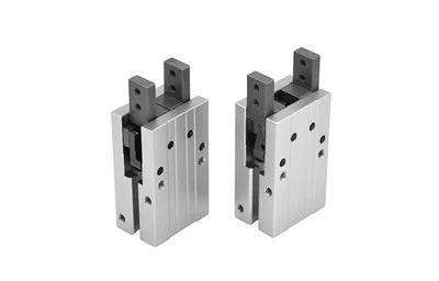
Product feature
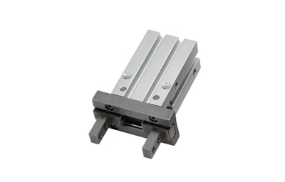
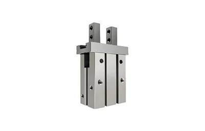
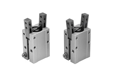
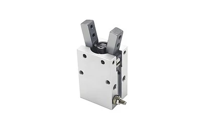
1.Six kinds of bore size , three kinds of type and Seven kinds of finger type.
2.Integrated design of linear guide roller, high rigidity and high precision.
3.A positioning pin is attached to the bottom of the linear guide rail, which can prevent the
deviation of the positioning rail and body.
4.The squareness magnetic switch slots convenient to install DS1-G,CS1-G type inducting
switch.
The roundness magnetic switch slots convenient to install DS1-H type inducting switch.
Can be mounted from three directions: With mounting holes on the side and tail.
5.With positioning hole:The positioning hole can improve the precision and the consistency of
repeated dismounting and positioning.
Specification
|
Bore size(mm) |
10 |
16 |
20 |
25 |
32 |
40 |
||
|
Acting type |
Double acting Single acting |
|||||||
|
Fluid |
Air(to be filtered by 40μm filter element) |
|||||||
|
Operating pressure |
Double acting |
Φ10 |
0.2~0.7MPa(28~100psi)(2.0~7.0bar) |
|||||
|
Others |
0.15~0.7MPa(22~100psi)(1.5~7.0bar) |
|||||||
|
Single acting |
Φ10 |
0.35~0.7MPa(50~100psi)(3.5~7.0bar) |
||||||
|
Others |
0.25~0.7MPa(36~100psi)(2.5~7.0bar) |
|||||||
|
Temperature℃ |
-20~70 |
|||||||
|
Lubrication |
Not required |
|||||||
|
Repeatability mm |
±0.01 |
±0.02 |
||||||
|
Max.frequency |
180(c.p.m) |
60(c.p.m) |
||||||
|
Sensor switches |
CMSH\DMSH |
CMSG\DMSG\EMSG CMSH\DMSH\EMSH |
||||||
|
Port size |
M3×0.5 |
M5×0.8 |
||||||
Gripping force and stroke
|
Acting type |
Double acting(HFK) |
||||||
|
Bore size |
10 |
16 |
20 |
25 |
32 |
40 |
|
|
Gripping force per finger Effective value(N) |
External |
11 |
34 |
45 |
69 |
160 |
255 |
|
Internal |
17 |
45 |
68 |
102 |
195 |
320 |
|
|
Opening/Closing stroke(Both sides)(mm) |
4 |
6 |
10 |
14 |
22 |
30 |
|
|
Weight (g) |
F Type |
56 |
124 |
236 |
418 |
750 |
1340 |
|
Others |
56 |
124 |
236 |
428 |
729 |
1268 |
|
Installation and application
1. Due to the abrupt changes,the circuit pressure is low, which will lead to the decrease of the gripping force and falling of the work-pieces.In order to avoid the harm to the human body and damage to the equipment, anti-dropping device must be equipped.
2. Don't use the air gripper under strong external force and impact force.
3. Please contact with us when the single acting type clamps only with the spring force.
4. When install and fix the air gripper, avoid falling down, collision and damage.
5.When fixing the gripping jaw parts, don't twist the gripping jaw.
6.There are several kinds of installation method, and the locking torque of fastening screw must be within the prescribed torque range shown in the below chart.If the locking torque is too large,it will cause the dysfunctional. If the locking torque is too small,it will cause the position deviation and fall.
7.The installation method of the gripping jaw fittings:
When install the gripping jaw fittings, you have to pay particular attention that you can only hold the gripping jaw by using spanner, and then lock the screws with allen wrench.Never clamp the body directly and then lock the screws, otherwise the parts will be easily damaged.
Confirm that there is no external forces exerted on the gripping jaw.Transverse load acts on the gripping jaw, which will cause impact load and leads to the shaking and damage of gripping jaw, Equip with gaps so that the air gripper will not crash into work-pieces and accessories at the end of its trip.
When the work-pieces are inserted,the center line should be coaxial, no offset,in case there are external force generated on griping jaw.When testing, it is specially required that the manual operation should be reduced, the pressure should be reduced to run it at a low speed, and guarantee the safety and no impact.
10. Please use the flow control valve to adjust the opening and closing speed of gripping jaw if too fast.
11. People can not enter the movement path of air gripper and articles can not be placed on the path too.
12. Before removing the air gripper, please confirm that it is out of working state, and then discharge of compressed air.
FAQ
Q: What are the 2 types of pneumatic cylinder?
Q: What is a pneumatic cylinder?
Q: What is a pneumatic gripper used for?
Hot Tags: hfk series pneumatic finger cylinder, China hfk series pneumatic finger cylinder manufacturers, suppliers, factory, hfkl series extended pneumatic finger cylinder, mhf2 thin gripper parallel, mhs series 2 finger pneumatic gripper, mhs series 3 finger pneumatic gripper, mhs series finger pneumatic air claw, robot parallel gripper cylinder for mask machine